Bluetooth Communication between Raspberry Pi and Arduino
Some Arduino boards have chip on board to support serial communication over USB, and will appear as a serial device when you connect them with your computer via USB cable. The USB connection can be used on not only uploading the sketch to Arduino board, but also exchanging data between Arduino and computer in real time.
Since Raspberry Pi is a full-featured mini computer, it can talk to Arduino as well, just like those big computers do. Connecting Raspberry Pi and Arduino with USB cable can do a lot of interesting things. We have a open-source project for developing the APIs for controlling Arduino in Raspberry Pi. This is very interesting and you can imagine many ways to use them. USB cable is neat enough if the major of cases. However, what if the Arduino needs to be placed far from the Raspberry Pi?
For example, if you want to put Arduino out of my window and you still want to control it with your Pi on desktop, what to do? A long USB cable may do the trick, if the distance is not that long. But if your Arduino is more than 2M further from your Pi, you should consider a wireless solution, such as using Bluetooth as a serial bridge.
Required Components
You will need the following components to implement such a wireless solution:
- Raspberry Pi
- Arduino Nano (or any other Arduino that has USB port on board)
- Bluetooth USB dongle
- SPP-CA Bluetooth serial module
Wiring Bluetooth Serial Module and Arduino
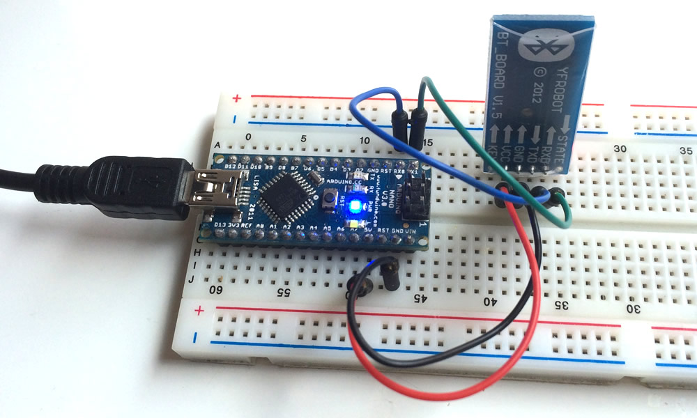
You can wire your Bluetooth serial module and your Arduino like this (we use Arduino Nano as example).
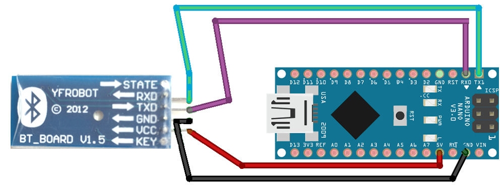
The Bluetooth serial module has 4 pins on board so it could be plugged into a breadboard. The USB plug in the figure below is just for power supply (DC 5V), and it has nothing to do with the communication.
Remarks: the SPP-CA Bluetooth serial module we use is 3~6V tolerated. If you use a Bluetooth module that only accept 3.3V, you will need to use voltage divider or level-translator between Arduino and the Bluetooth module.
Source Code on Arduino Side
You can use the source code below for testing the Bluetooth module. Before you upload the sketch, make sure to temporarily break the TX/RX wiring between the Bluetooth module and Arduino, or they will affect each other and the uploading will fail.
int ledPin = 13;
void setup() {
  Serial.begin( 9600 );    // 9600 is the default baud rate for the serial Bluetooth module
}
void loop() {
  // listen for the data
  if ( Serial.available() > 0 ) {
    // read a numbers from serial port
    int count = Serial.parseInt();
     // print out the received number
    if (count > 0) {
        Serial.print("You have input: ");
        Serial.println(String(count));
        // blink the LED
        blinkLED(count);
    }
  }
}
void blinkLED(int count) {
  for (int i=0; i< count; i++) {
    digitalWrite(ledPin, HIGH);
    delay(500);
    digitalWrite(ledPin, LOW);
    delay(500);
  }
}
Pair the Bluetooth USB Dongle with Bluetooth Serial Module
Now let’s work on the Raspberry Pi side. Plug the Bluetooth dongle into Raspberry Pi’s USB port.
Run the following commands on your Pi:
sudo apt-get update
sudo apt-get install bluetooth bluez-utils blueman
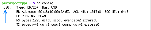
Then you can get the device name of your Bluetooth USB dongle by running the “hciconfig” command.
hciconfig
The Bluetooth dongle device name looks like “hci0” or “hci1“, in the example below, it is “hci0”:
Now you can search the serial bluetooth module by following command
hcitool scan
It could take a few seconds to discover all Bluetooth devices nearby. The address and name of your Bluetooth module should be listed:

The Bluetooth module that connects with Arduino and the Bluetooth dongle connects with Raspberry Pi need to be paired before making actual communication. The pairing can be done by running the following command:
sudo bluez-simple-agent hci# xx:xx:xx:xx:xx:xx
The # is the number of your device (probably be 0 if you have only one bluetooth dongle connected) and xx:xx:xx:xx:xx:xx is the address of the serial Bluetooth module. After a few seconds, the program should ask you for the pin code of the Bluetooth module. By default, the pin for this module is 1234, and this password could be modified in AT mode.
Now we have 2 devices that can communicate with each other via Bluetooth protocol. However we still need to set up another protocol over the Bluetooth, which is named RFCOMM to emulate the serial connection between these two devices. The protocol setup could be done by modifying the “rfcomm.conf” file.
sudo nano /etc/bluetooth/rfcomm.conf
Append the following lines to the file:
rfcomm1 {
    bind yes;
    device xx:xx:xx:xx:xx:xx;
    channel 1;
    comment "Connection to Bluetooth serial module";
}
Here xx:xx:xx:xx:xx:xx is the address of Bluetooth module.
Save the file and run this command:
sudo rfcomm bind all
Then you will see the device “/dev/rfcomm1” appeared.
Python Code on Raspberry Pi
If you haven’t installed pySerial before, you should do it now:
sudo apt-get install python-serial
Save the content below as file “bluetooth_serial_test.py”:
#! /usr/bin/python
import serial
from time import sleep
bluetoothSerial = serial.Serial( "/dev/rfcomm1", baudrate=9600 )
count = None
while count == None:
    try:
        count = int(raw_input( "Please enter the number of times to blink the L$
    except:
        pass    # Ignore any errors that may occur and try again
bluetoothSerial.write( str(count) )
print bluetoothSerial.readline()
Then you can run it with:
python bluetooth_serial_test.py
It will prompt you to input a number N, and then you will see the LED blinks N times and the message “You have input: N” is printed in your console.
 If you get the same result, it proves the serial communication over bluetooth is working on both directions. Congratulations! 🙂
