UPDATE ON 2016.08.03:
This tutorial was written for Witty Pi (1st generation), however the approach can be used on Witty Pi 2 as well. Please kindly notice that, in Witty Pi 2’s software, we do not use wiringPi naming anymore, and instead use BCM naming everywhere. So you will see GPIO-4 is pin 4, and GPIO17 is pin 17 when you are editing Witty Pi 2’s script.
By default, Witty Pi uses GPIO-4 to detect the switching off signal and GPIO17 to drive the white LED on board. This configuration works in the major of cases. However, if you are using a third-party board that already uses any of these two pins, you may want to change the pin that used by Witty Pi. Fortunately it is not difficult to achieve.
Change Pin for the White LED
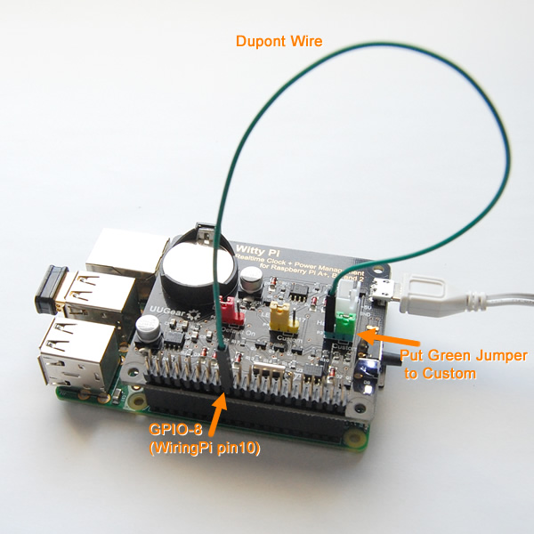
If you want to choose a different pin to drive the white LED on Witty Pi, it is quite simple and basically any available pin could be used for this purpose. Just put the yellow jumper on the “Custom” position, and use a dupont wire to connect the remaining jumper pin and the new pin you selected.

Then you need to modify the “daemon.sh” file, to use the new pin to light up the white LED on board.
For example, if you wish to use GPIO-18 instead of the default GPIO-17 pin to drive the LED, you will modify the “daemon.sh” file as shown below.
#!/bin/bash# file: daemon.sh
#!/bin/bash
# file: daemon.sh
#
# This script should be auto started, to support WittyPi hardware
#
# check if sudo is used
if [ "$(id -u)" != 0 ]; then
  echo 'Sorry, you need to run this script with sudo'
  exit 1
fi
# get current directory
cur_dir=$(cd "$(dirname "${BASH_SOURCE[0]}")" && pwd)
# utilities
. "$cur_dir/utilities.sh"
log 'Witty Pi daemon (v2.13) is started.'
# halt by GPIO-4 (wiringPi pin 7)
halt_pin=7
# LED on GPIO-18 (wiringPi pin 1)
led_pin=1
# if RTC presents
has_rtc=is_rtc_connected
if $has_rtc ; then
  # disable square wave and enable alarm B
  i2c_write 0x01 0x68 0x0E 0x07
  # clear alarm flags
  byte_F=$(i2c_read 0x01 0x68 0x0F)
  byte_F=$(($byte_F&0xFC))
  i2c_write 0x01 0x68 0x0F $byte_F
else
  log 'Witty Pi is not connected, skipping I2C communications...'
fi
# delay until GPIO pin state gets stable
counter=0
while [ $counter -lt 5 ]; do
  if [ $(gpio read $halt_pin) == '1' ] ; then
    counter=$(($counter+1))
  else
    counter=0
  fi
  sleep 1
done
# wait for GPIO-4 (wiringPi pin 7) falling, or alarm B
log 'Pending for incoming shutdown command...'
gpio wfi $halt_pin falling
log 'Shutdown command is received...'
# light the white LED
gpio mode $led_pin out
gpio write $led_pin 1
# restore GPIO-4
gpio mode $halt_pin in
gpio mode $halt_pin up
if $has_rtc ; then
  # clear alarm flags
  byte_F=$(i2c_read 0x01 0x68 0x0F)
  byte_F=$(($byte_F&0xFC))
  i2c_write 0x01 0x68 0x0F $byte_F
  # only enable alarm A
  i2c_write 0x01 0x68 0x0E 0x05
fi
log 'Halting all processes and then shutdown Raspberry Pi...'
# halt everything and shutdown
shutdown -h now
The only change is on line 25 and 26, where we modify the pin number from 0 to 1. Since GPIO-18 is pin 1 in wiringPi, while GPIO-17 is pin 0 in wiringPi.
Change Pin for Switching Off Your Pi
By default Witty Pi listens to GPIO-4 (pin 7 in wiringPi). If it drop to low voltage, Witty Pi will start the shutdown procedure. If you want to use a different pin for this purpose, you need to choose a pin that:
- gets initiated as input pin
- has default HIGH state
How to find a good alternative pin? The simplest way I found is to run “gpio readall” after starting your Pi. It will print out all pin status in a very clean way:
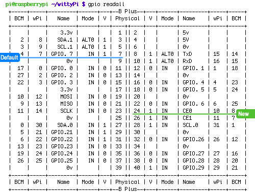
Here we choose GPIO-8 to replace GPIO-4. The wiring looks like this:
The last step is to update the “daemon.sh” script. Here is the modified code:
#!/bin/bash
# file: daemon.sh
#
# This script should be auto started, to support WittyPi hardware
#
# check if sudo is used
if [ "$(id -u)" != 0 ]; then
  echo 'Sorry, you need to run this script with sudo'
  exit 1
fi
# get current directory
cur_dir=$(cd "$(dirname "${BASH_SOURCE[0]}")" && pwd)
# utilities
. "$cur_dir/utilities.sh"
log 'Witty Pi daemon (v2.13) is started.'
# halt by GPIO-8 (wiringPi pin 10)
halt_pin=10
# LED on GPIO-17 (wiringPi pin 0)
led_pin=0
# if RTC presents
has_rtc=is_rtc_connected
if $has_rtc ; then
  # disable square wave and enable alarm B
  i2c_write 0x01 0x68 0x0E 0x07
  # clear alarm flags
  byte_F=$(i2c_read 0x01 0x68 0x0F)
  byte_F=$(($byte_F&0xFC))
  i2c_write 0x01 0x68 0x0F $byte_F
else
  log 'Witty Pi is not connected, skipping I2C communications...'
fi
# delay until GPIO pin state gets stable
counter=0
while [ $counter -lt 5 ]; do
  if [ $(gpio read $halt_pin) == '1' ] ; then
    counter=$(($counter+1))
  else
    counter=0
  fi
  sleep 1
done
# wait for GPIO-4 (wiringPi pin 7) falling, or alarm B
log 'Pending for incoming shutdown command...'
gpio wfi $halt_pin falling
log 'Shutdown command is received...'
# light the white LED
gpio mode $led_pin out
gpio write $led_pin 1
# restore GPIO-4
gpio mode $halt_pin in
gpio mode $halt_pin up
if $has_rtc ; then
  # clear alarm flags
  byte_F=$(i2c_read 0x01 0x68 0x0F)
  byte_F=$(($byte_F&0xFC))
  i2c_write 0x01 0x68 0x0F $byte_F
  # only enable alarm A
  i2c_write 0x01 0x68 0x0E 0x05
fi
log 'Halting all processes and then shutdown Raspberry Pi...'
# halt everything and shutdown
shutdown -h now
Only line 21 and 22 are changed, please notice that GPIO-8 is pin 10 in wiringPi, while GPIO-4 is pin 7 in wiringPi.
That’s it, after rebooting your Witty Pi will be functional with the new pins 😀