Witty Pi Mini is our new product. It has the same functionality with Witty Pi 2, while it has the same size with Raspberry Pi Zero (W). With Witty Pi Mini and Raspberry Pi Zero (W) you can make more compact portable device.
There is still a problem though, just like any model of Raspberry Pi, Witty Pi Mini can only accept DC 5V power supply. This become quite challenging when making a portable device, as we don’t have any battery that can directly output 5V.
The Simplest Solution
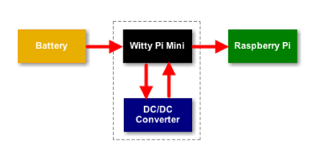
If you want to power your Witty Pi Mini + Raspberry Pi with battery, you can use a DC/DC module to convert the battery voltage to 5V, as shown in figure below:

This will work as expected, but it is not perfect because the power switch on Witty Pi Mini can not turn off the DC/DC converter. As a result, the DC/DC converter will keep running and continue drawing some current from the battery, even if the Raspberry Pi is totally off. This actual static current consumption depends on the DC/DC module you use. Usually you can expect a few mAs, or dozens of mAs static current consumption. If this kind of static current consumption is acceptable, then this solution is good for you.
The Advanced Solution
If you are using a rather small battery, you may want to save any current consumption if possible. So, is it possible to save that static current consumption from DC/DC converter?
Yes! It is possible to achieve this by integrating the DC/DC module into Witty Pi Mini, and let Witty Pi Mini to control the on/off of the DC/DC converter as well. The wiring becomes:
As you can see, the battery is now directly connected Witty Pi Mini. This is allowed only if the voltage of battery is lower than 5V, as Witty Pi Mini is designed to work under 5V. A single cell LiPo battery will be ideal, who is 3.7V (or 4.2V after fully charged). We will need to use DC/DC step-up (boost) module to convert the voltage to 5V, and then supply to Raspberry Pi.
Although Witty Pi Mini is designed for 5V, its e-latching power switch can actually work down to ~2V. If we use single cell LiPo battery, its actually voltage will be 3~4.2V, so we are sure the power switch can still work directly with the battery.
What about the RTC? It needs to work even after Raspberry Pi is off, so it should be powered directly by the battery. According to the RTC chip’s datasheet. The RTC on Witty Pi Mini can work under 2.3~5.5V, so using a single cell LiPo battery to power it will not bring any problem.
In this tutorial we choose this DC/DC boost module, which has adjustable output voltage and can output up to 2A current. It is quite small (30mm x 17mm x 6.5mm) and is very suitable to be integrated into Witty Pi Mini. Before starting the integration, we need to adjust the output voltage of this DC/DC module, to make sure it outputs 5V. The diagram below shows how to do:
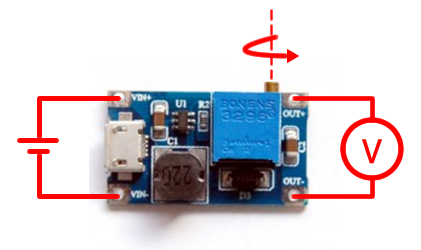
The battery can be a single cell LiPo battery, or you can use an adjustable power supply to output 3.7V to emulate it. You can use a multimeter to monitor the output voltage, or you may consider using this mini voltage meter. If you find the output voltage is always the same with the input voltage, you can use a small screw driver to adjust the potentiometer clock-wise, for about 20 circles. Once you see the voltage is increasing, slow down the adjusting, and make sure the output voltage will be 5~5.2V. After finishing the adjustment, if you prefer, you can use hot melt glue to seal the handle of the potentiometer, to avoid changing the output voltage unintentionally.
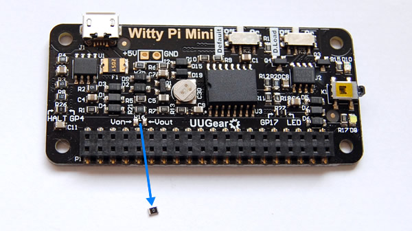
We will then unsolder the R16 on Witty Pi Mini, you can use a hot-air gun or soldering iron to do so. R16 is a zero Ohm resistor and it connects the Von and Vout net. Von is the voltage comes out from the power switch, it equals to the input voltage when the power switch is on; Vout is the voltage to power Raspberry Pi, and it connects to the +5V pin in the GPIO header. When R16 is soldered on its place, Von and Vout are connected. Now we remove R16 and will put the DC/DC module between Von and Vout.
We will solder three wires between Witty Pi Mini and the DC/DC converter module. The Von pad should be connected to the VIN+ pad on the DC/DC board, while the Vout pad should link to the OUT+ pad. We need to connect the GND for both boards, we choose to solder the black wire (GND) to the left-top pin in the 40-pin header, which is connected to GND of the entire circuit. The black wire connects to the VIN- pad on the DC/DC board, which also connects to the OUT- pad as well. We also solder a 2-pin header for connecting the battery.
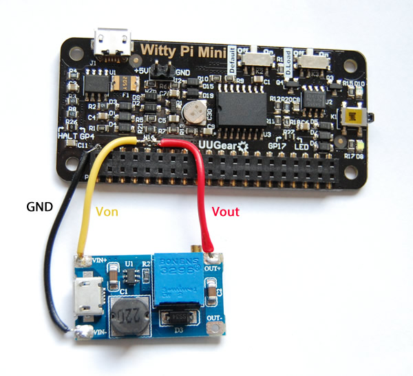
After this modification, the DC/DC module will get powered once the power switch on Witty Pi Mini is turned ON, and it will output 5V to power your Raspberry Pi and connected USB device (if there is any). On the other hand, after Raspberry Pi is turned off, the power for DC/DC module will be cut as well, and it will not consume any current.
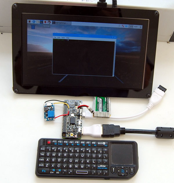
For demonstration, we connect a single cell LiPo battery (3.7V, 750mAh) to Witty Pi Mini, and use OTG adapter to connect the wireless keyboard dongle to Raspberry Pi Zero. An HDMI display is connected too, and it is powered by external power supply. The small battery can power Raspberry Pi Zero for about 2 hours.
This modified Witty Pi Mini can be used on Raspberry Pi 3 too. In the video below you can see the modified Witty Pi Mini connects to Raspberry Pi 3 via the stacking GPIO header. The display is powered by an external power adapter, because it requires too many current at startup, and the DC/DC converter and the battery can’t supply that much.
Witty Pi Mini + Raspberry Pi Zero (W) doesn’t have to run a desktop environment. Especially for Raspberry Pi Zero W, it has WiFi built-in and can work as a wireless server already. Using battery to power it will be very handy: you don’t need to connect keyboard, mouse and display to it. When you want to access your Pi Zero W, just establish an SSH connection from your computer.
Note: If your Witty Pi Mini can not wake up your Raspberry Pi after this modification, you can try increasing the value of C5 (the 47uF ceramic capacitor on the left of the supper capacitor). You can either replace it with bigger capacitor (e.g. 100uF electrolytic capacitor), or you can just connect the bigger capacitor to C5 in parallel.