This tutorial helps you to compile and flash firmware into Witty Pi 4 boards, including the full-sized Witty Pi 4, Witty Pi 4 Mini and Witty Pi 4 L3V7.
If you just want to flash the firmware, you may directly jump to that part.
Collect Information from Your Board
It is a good practice to collect some information from your board first.
Current firmware revision
When your Witty Pi is mounted on Raspberry Pi, and your Pi is running, you may use this command to get Witty Pi’s firmware revision:
i2cget -y 1 8 12
This command will print out a hexadecimal number, and that is the revision number of firmware.
You may also find the firmware revision from the wittyPi.log file. This information is printed everytime your Pi is boot.
Remmber this number. If in the future you want to revert back to previous firmware, you need to know its revision number.
RTC offset value
When your Witty Pi is mounted on Raspberry Pi, and your Pi is running, you may use this command to get the RTC offset value:
i2cget -y 1 8 37
The result is a hexadecimal number, and this number is used to adjust your RTC (to make it more accurate).
Starting from V4.2, Witty Pi’s software will also log this offset value to the wittyPi.log file. This information is printed everytime your Pi is boot.
When we flash the firmware, we will erase the data in EEPROM. This value is the only data we want to restore after the firmware update.
Compile Firmware
If you want to modify the firmware according to your requirements, you will need to compile the firmware by yourself. The firmware can be compiled with Arduino IDE.
After installing Arduino IDE (recommand V1.8.19 or higher), you need to turn on its verbose output and specify the additional board manager URL. The screenshot below shows the preference settings for Arduino IDE in Mac OS X, you should find very similar settings in Windows.
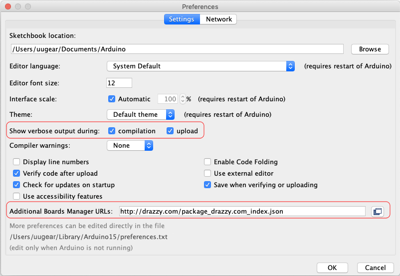
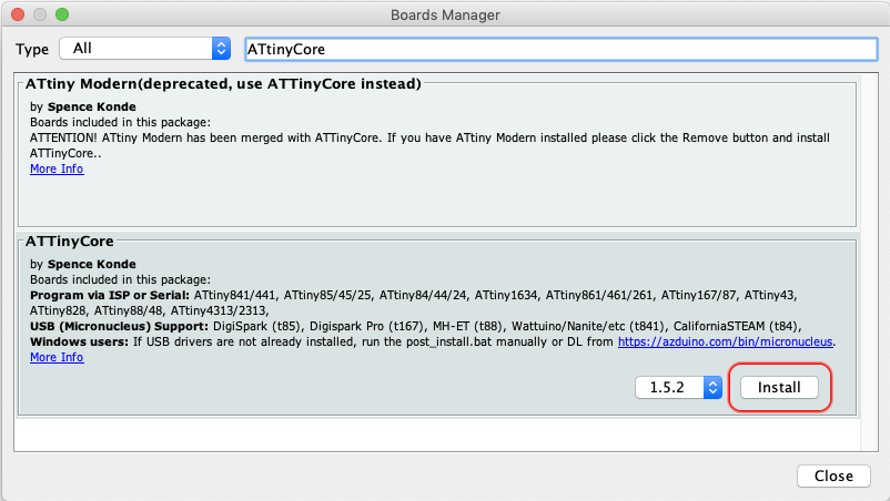
You will need ATtinyCore (V1.5.2) to compile the firmware. To install it, you specify the URL “http://drazzy.com/package_drazzy.com_index.json” as the addtional board manager URL. If you already have other URLs in this field, use comma to separate them.
Go to menu Tools->Board->Boards Manager…, and then search “ATtinyCore”, click the “Install” button to proceed.
After the installation you can choose the board type from menu Tools->Board->ATtinyCore->ATtiny441/841 (No bootloader), and then you configure the board under the “Tools” menu as shown below:
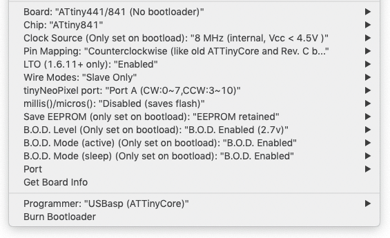
Carefully check all settings here, they equals to set the fuses to E:F5, H:DD, L:E2, which turns on the B.O.D. (brown-out detection) at 2.7V, to protect the data stored in the MCU.
Remarks: if you are compiling firmware (rev 6 or below) for Witty Pi 4 L3V7, the “mills()/micros()” option should be enabled, because Witty Pi 4 L3V7’s firmware (rev 6 or below) is still using the micros() function. For firmware rev 7 or above, the “mills()/micros()” option should be disabled as for other models.
You can find the latest firmware source code from the our GitHub repository. You will the SoftIICMaster.h and SoftWireMaster.h files in the same directory as the .ino file.
Remarks: Witty Pi 4 Mini shares the same source code with full-sized Witty Pi 4, just manually change the firmware ID from 0x26 to 0x36.
Now you can compile the firmware from menu Sketch->Verify/Compile. Check the log output and you will see something like this at the bottom:
/Users/uugear/Library/Arduino15/packages/arduino/tools/avr-gcc/7.3.0-atmel3.6.1-arduino7/bin/avr-size -A /var/folders/j3/bcqz5xv531j_3cb0bxqbqbq00000gn/T/arduino_build_418439/WittyPi4.ino.elf
Sketch uses 7848 bytes (95%) of program storage space. Maximum is 8192 bytes.
Global variables use 224 bytes (43%) of dynamic memory, leaving 288 bytes for local variables. Maximum is 512 bytes.
Here you can find the output directory, which stores the compiled firmware (.hex file). In this example, the output directory is “/var/folders/j3/bcqz5xv531j_3cb0bxqbqbq00000gn/T/arduino_build_418439/”, if you open that directory, you will find the “WittyPi4.ino.hex” file there.
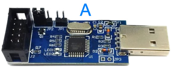
If you have USBasp programer, you may also use it to directly upload the firmware to your Witty Pi board from Arduino IDE. You need to select “USBasp (ATTinyCore)” programmer under the “Tools” menu. Here you may find details about how to physically connect your USBasp to Witty Pi board.
Flash Firmware into the Board
Get the compiled firmware
If you have went through the previous “Compile Firmware” section, you already have the compiled firmware, which is an .hex file.
If you just want to reflash the firmware or upgrade the firmware to newer version, you can download the pre-compiled firmware files from our GitHub repository. Below are the download links for pre-compiled firmware for specific boards:
- For Witty Pi 4: WittyPi4.ino.hex
- For Witty Pi 4 Mini: WittyPi4_Mini.ino.hex
- For Witty Pi 4 L3V7: WittyPi4_L3V7.ino.hex
You can right click the link and choose “Save Link As…” in the pop-up menu, to save the .hex file into the directory you choose.
Install avrdude (on proper OS)
You will need avrdude command to flash the firmware, which is not installed by default.
If you will use USBasp programmer to flash the firmware, you may just install avrdude with this command on any version of Raspberry Pi OS:
sudo apt-get install avrdude
You may then run “avrdude -v” to confirm the version of avrdude. It should be version 6.3 for Bullseye and version 7.1 for Bookworm.
If you will use your Raspberry Pi to emulate an ICSP programmer, at the moment that I write this tutorial, it only works on Bullseye or lower. This is because Bullseye comes with with kernel 6.1 while Bookworm comes with kernel 6.6, and kernel 6.5 and onward have removed sysfs, which is used by avrdude’s “linuxgpio” programmer. The avrdude development team is aware of this situation, but there seems no good solution at the moment. At the time being the avrdude on Bookworm doesn’t support linuxgpio and hence the work in this chapter can only be done under Bullseye or lower. If you are using Bookworm OS on your Raspberry Pi, you will need to find another SD card and install Bullseye OS into it, and use that SD card to continue the work.
Flash the firmware with USBasp
You will need a programmer to flash the firmware file into your Witty Pi board. You may use a programmer like USBasp. If you don’t have USBasp, you may use your Raspberry Pi to emulate an ICSP programmer.
Check your USBasp programmer to see if it comes with extension cable (B) and ICSP adapter board (C).
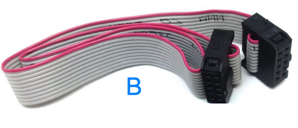
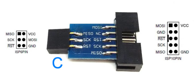
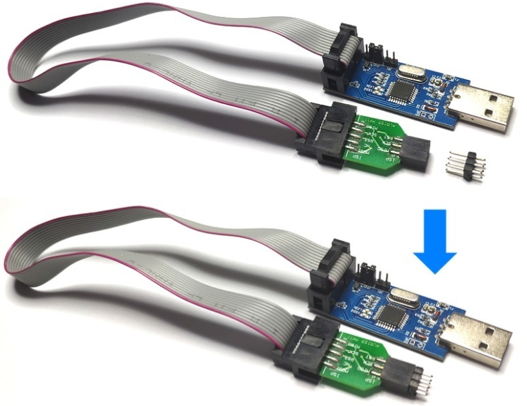
If you USBasp comes with the cable (B) and ICSP adapter board (C), you can put an ICSP pin header (pitch 2.54mm, 2x3P) on the adapter board and make it a “firmware updating plug”.
This plug can be plugged into Witty Pi’s ICSP footprint, and then you can use finger to gently press it to one side so that all 6 pins will get well connected. This way you don’t have to solder an ICSP header on your Witty Pi board.

Please notice that, for full-sized Witty Pi 4, you will plug it from top side of the board; for Witty Pi 4 Mini and Witty Pi 4 L3V7, you will plug it from bottom side of the board because the ICSP footprint is underneath the MCU.
If your USBasp programmer doesn’t come with extension cable (B) or the ICSP adapter board (C), you will need 6 DuPont wires to make a firmware updating plug.
If you use 6 female-female DuPont wires, you also need to plug a 2×3 header to one end to make it a plug:
If you use 6 female-male DuPont wires, you can use a rubber band to tie up their male ends with proper layout, to make it a plug:

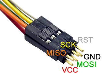
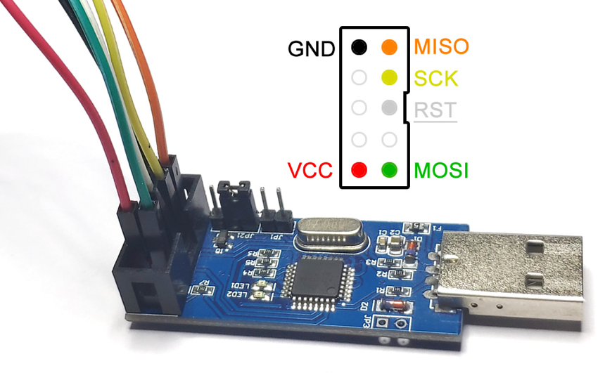
In both cases the wiring on USBasp side will look like this:
Now connect USBasp to the USB port on your Raspberry Pi, and go to the directory that contains the compiled firmware (.hex file).
Run this command to flash the firmware into the board:
avrdude -C /etc/avrdude.conf -v -pattiny841 -cusbasp -e -Uefuse:w:0xF5:m -Uhfuse:w:0xDD:m -Ulfuse:w:0xE2:m -Uflash:w:./WittyPi4.ino.hex:i
This command is for full-sized Witty Pi 4. If you are flashing firmware for Witty Pi 4 Mini or Witty Pi 4 L3V7, just replace the “WittyPi4.ino.hex” with “WittyPi4_Mini.ino.hex” or “WittyPi4_L3V7.ino.hex” accordingly.
This command also set the fuses (-Uefuse:w:0xF5:m -Uhfuse:w:0xDD:m -Ulfuse:w:0xE2:m) to turn on the B.O.D. (brown-out detection), to protect the data in MCU when input voltage is lower than 2.7V.
If the command runs succesfully, the firmware has been flashed into your Witty Pi board. You can now disconnect the firmware updating plug from your Witty Pi. It is recommended to restore the RTC offset value afterward.
Flash the firmware with Raspberry Pi Emulated Programmer
If you do not have USBasp, you may use Raspberry Pi to emulate an ICSP programmer. You will need 6 DuPont wires to connect your Raspberry Pi and Witty Pi board.
If you use 6 female-female DuPont wires, you also need to plug a 2×3 header to one end to make it a plug:
If you use 6 female-male DuPont wires, you can use a rubber band to tie up their male ends with proper layout, to make it a plug:
This plug can be plugged into Witty Pi’s ICSP footprint, and then you can use finger to gently press it to one side so that all 6 pins will get well connected. This way you don’t have to solder an ICSP header on your Witty Pi board.
Please notice that, for full-sized Witty Pi 4, you will plug it from top side of the board; for Witty Pi 4 Mini and Witty Pi 4 L3V7, you will plug it from bottom side of the board because the ICSP footprint is underneath the MCU.
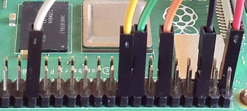
The other ends of DuPont wires are connected to the GPIO-header on the Raspberry Pi, as shown in picture below:
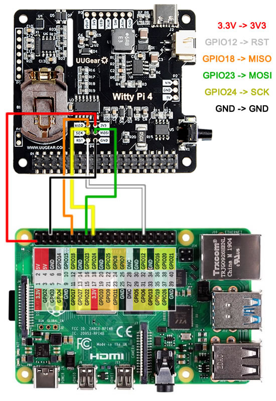
Please also see below the wiring plan for Witty Pi 4. For Witty Pi 4 Mini and Witty Pi 4 L3V7, the plan is the same but will wire to the bottom side of the board.
Now you need to tell avrdude that you are using GPIOs as programmer. The default configuration file for avrdude is /etc/avrdude.conf, but it is better not to modify this file directly. You can make a copy of this file in your home directory, and then edit that copy:
cp /etc/avrdude.conf ~/avrdude_gpio.conf
nano ~/avrdude_gpio.conf
Please append these lines at the end of the file:
# Linux GPIO configuration for avrdude.
# Change the lines below to the GPIO pins connected to the AVR.
programmer
  id    = "RasPi";
  desc  = "Use the Linux sysfs interface to bitbang GPIO lines";
  type  = "linuxgpio";
  reset = 12;
  sck   = 24;
  mosi  = 23;
  miso  = 18;
;
To quit the nano editor, you press Ctrl+X, and then press Y and Enter to save the file.
You can then run this command to verify the configuration:
sudo avrdude -p attiny841 -C ~/avrdude_gpio.conf -c RasPi -v
If everything is OK, it will print something like this:
avrdude: Version 6.3-20171130
         Copyright (c) 2000-2005 Brian Dean, http://www.bdmicro.com/
         Copyright (c) 2007-2014 Joerg Wunsch

         System wide configuration file is "/home/pi/avrdude_gpio.conf"
         User configuration file is "/root/.avrduderc"
         User configuration file does not exist or is not a regular file, skipping

         Using Port                    : unknown
         Using Programmer              : RasPi
         AVR Part                      : ATtiny841
         Chip Erase delay              : 4500 us
         PAGEL                         : P00
         BS2                           : P00
         RESET disposition             : possible i/o
         RETRY pulse                   : SCK
         serial program mode           : yes
         parallel program mode         : yes
         Timeout                       : 200
         StabDelay                     : 100
         CmdexeDelay                   : 25
         SyncLoops                     : 32
         ByteDelay                     : 0
         PollIndex                     : 3
         PollValue                     : 0x53
         Memory Detail                 :

                                  Block Poll               Page                       Polled
           Memory Type Mode Delay Size  Indx Paged  Size   Size #Pages MinW  MaxW   ReadBack
           ----------- ---- ----- ----- ---- ------ ------ ---- ------ ----- ----- ---------
           eeprom        65     6     4    0 no        512    4      0  4000  4500 0xff 0xff
           signature      0     0     0    0 no          3    0      0     0     0 0x00 0x00
           lock           0     0     0    0 no          1    0      0  9000  9000 0x00 0x00
           lfuse          0     0     0    0 no          1    0      0  9000  9000 0x00 0x00
           hfuse          0     0     0    0 no          1    0      0  9000  9000 0x00 0x00
           calibration    0     0     0    0 no          1    0      0     0     0 0x00 0x00
           flash         65     6    16    0 yes      8192   16    512  4500  4500 0xff 0xff
           efuse          0     0     0    0 no          1    0      0  9000  9000 0x00 0x00

         Programmer Type : linuxgpio
         Description     : Use the Linux sysfs interface to bitbang GPIO lines
         Pin assignment  : /sys/class/gpio/gpio{n}
           RESET   =  12
           SCK     =  24
           MOSI    =  23
           MISO    =  18
......
If you have Witty Pi connected to the firmware updating plug while running this command, it should not print any error, otherwise it may complain “AVR device not responding”.
Reminder: at the moment that I write this tutorial, this only works on Bullseye or lower. If you use Bookworm, the “linuxgpio” programmer is not supported by the avrdude.
Now you are ready to flash the firmware. Go to the directory that contains the compiled firmware (.hex file), make sure the firmware updating plug is connected to your Witty Pi, and run this command:
sudo avrdude -p attiny841 -C ~/avrdude_gpio.conf -v -c RasPi -e -Uefuse:w:0xF5:m -Uhfuse:w:0xDD:m -Ulfuse:w:0xE2:m -Uflash:w:./WittyPi4.ino.hex:i
This command is for full-sized Witty Pi 4. If you are flashing firmware for Witty Pi 4 Mini or Witty Pi 4 L3V7, just replace the “WittyPi4.ino.hex” with “WittyPi4_Mini.ino.hex” or “WittyPi4_L3V7.ino.hex” accordingly.
This command also set the fuses (-Uefuse:w:0xF5:m -Uhfuse:w:0xDD:m -Ulfuse:w:0xE2:m) to turn on the B.O.D. (brown-out detection), to protect the data in MCU when input voltage is lower than 2.7V.
If the command runs succesfully, the firmware has been flashed into your Witty Pi board. You can now disconnect the firmware updating plug from your Witty Pi. It is recommended to restore the RTC offset value afterward.
Restore the RTC offset value
After flashing the firmware to Witty Pi, the RTC offset value is set to 0x00, which will make the RTC timing less accurate. It is recommended to restore the RTC offset value, which was collected in eariler step.
You need to mount your Witty Pi on Raspberry Pi, so it can connect to the I2C bus on your Pi.
For example, if you previously read the RTC offset value is 0x77, now you can restore it with this command:
i2cset -y 1 8 37 0x77
Remember to replace 0x77 with the actual RTC offset value you have. After this command succesfully run, you have restored the RTC offset value and your RTC will tick as accurate as before.