
HI folks....I have a PI 5 and the Witty PI 4 L3V7. The L3V7 will be a standalone. From what I understand 4 wires are only required to "talk" to the L3V7 board to set item #11 to "1" which will always instruct the Witty board that senses 5V at the USB micro to automatically output 5v at P3-1 and P3-6. I need the pin to pin assignment (Witty to PI 5) since as noted its a standalone. I gather the there only needs 4 wires wires totally to update the board and then once updated, the wires will be removed. The 4 wires I believe the wires are : 5V (pin 2), GND (pin 6), SDA (pin 3) and SCL (pin 5). Commands are via the ssh terminal in Windows 11. Also please note the code to down load. Additionally if its found the there is no I2C (ALL DASHES) at the Witty meaning the PI 5 can't see the board what happens next assuming the 4 wires are good connections? I am using the Adafruit 27W power supply. Thanks for your time
I have read a bit and I see the following noted as probable wire point to point connections after going thru the manual.
1) Power to Witty board via USB micro using Adafruit P/S
2) Witty P3-1 to PI pin 4 (power the PI)
3) Witty P3-6 to PI pin 9 (power the PI)
4) Witty pin 3 to PI pin 3
5) Witty pin 5 to PI pin 5
6) Witty pin 11 to to PI pin 11
7) Witty pin 7 to PI pin 7
8) Witty pin 8 to to PI pin
Item 6 above Boot handshake
Item 7 above Shutdown trigger
Item 8 above shutdown complete
Not sure if items 6 thru 8 are really needed...comments would be great
My only goal for now is to change the setting on the Witty board (#11, set to "1" if the PI ever sees the the Witty I2C which it hasn't, all dashes) the Witty board will now switch the 5V at USB micro in to the P3 points....also battery back up is required but that should be the board's functionality....
Thanks Jay

Since you only want to change the “Default state when powered” setting once, there is no need to create a point-to-point wiring setup just to change this setting.
Just install the Witty Pi 4 L3V7 normally on the Raspberry Pi 5, power the system through Witty Pi 4 L3V7 only, install the Witty Pi software according to the user manual, run wittyPi.sh, and select:
11 → 1 → 1
Then shut the Pi down normally, disconnect the power, and remove the L3V7. The setting is stored in EEPROM and will remain after the board is removed.
If you power the Raspberry Pi directly instead, the L3V7 MCU is not powered and it is normal that its I²C device does not appear. (a reference in the forum)
There is therefore no need to determine which subset of the 40-pin connections is required for this one-time configuration.
@admin Thank you for that suggestion and it made sense to do it as you noted since its just that one parameter. The test revealed the I2C is not functioning.
Plugged PI 4 Witty L3V7 onto PI 5 after removing the Active cooler
Powered L3V7 via its own USB-C input (no battery connected) with Adafruit 27W P/S
Pushed button, Pi 5 booted
jay@raspberrypi:~ $ i2cdetect -y 1
Error: Could not open file `/dev/i2c-1' or `/dev/i2c/1': No such file or directory
(I2C not yet enabled — enabled via sudo raspi-config → Interface Options → I2C → Yes, then rebooted)
jay@raspberrypi:~ $ sudo raspi-config
jay@raspberrypi:~ $ sudo reboot
jay@raspberrypi:~ $ i2cdetect -y 1
The results are seen in the attached jpg
Thank you for the suggestion.
Jay
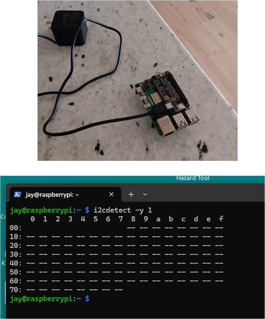
@jaykay Since the L3V7 can power on the Pi 5 when you press the button, the MCU is running, so an isolated firmware/I2C-stack failure would be very unlikely.
From your photo, it looks like the 40-pin header may not be fully seated. The power pins can make contact while one or both I2C pins still do not.
Please shut down the Pi, disconnect the USB-C power completely, and then press the L3V7 down evenly on the 40-pin header so it is firmly seated.
If you prefer to leave the header slightly less than fully seated so that the L3V7 is easier to remove later, that is fine. However, please make sure the Raspberry Pi header pins are inserted far enough that the tops of the pins are visible at the top of the L3V7 female header. Otherwise some contacts, including SDA/SCL, may not make a reliable connection.
Then power it again, boot the Pi and retry:
i2cdetect -y 1
If it still shows all dashes, please also post the output of:
gpio readall
There is no need to connect a battery for this test.
@admin OK....I'll rerun the test...the board was not fully seated is because the board itself was bending due to physical interference. I did not want to flex the board as that could impact tracks on/within the boarding depending on the number of layers and also could affect possible solder connection(s).
Jay
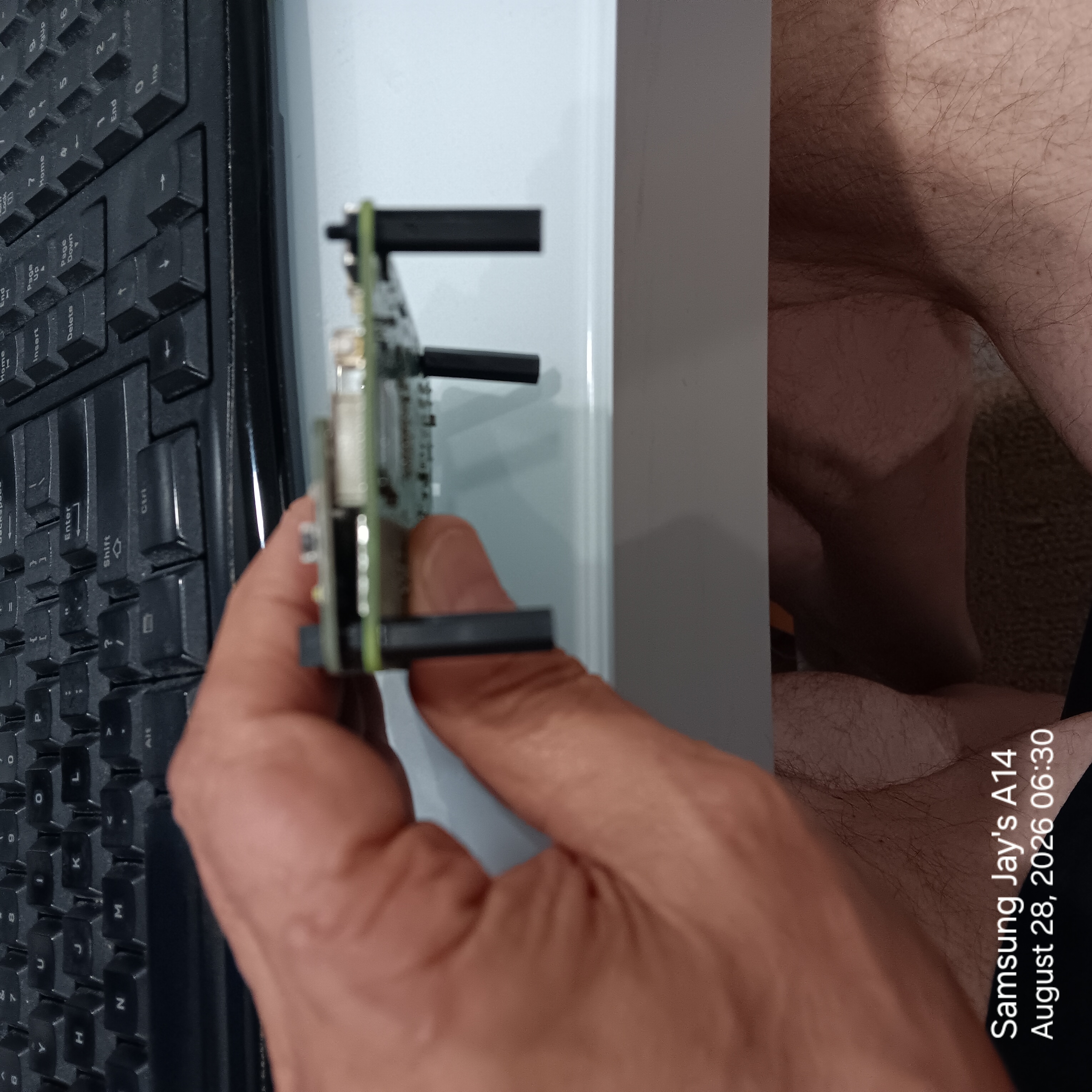
OK...I'll rerun the test a little later on this morning. The issue was noticed while mating the card. Its not flexing as I had originally thought but actual pitching of the card fully mounted and how the card was actually coming into contact with a PI connector at it right side, rear. Pix a little out of focus but it can be seen the pins in the mating will be pitched....that's not ideal as I see it.
Lets see what happens
Thanks for response.
Jay
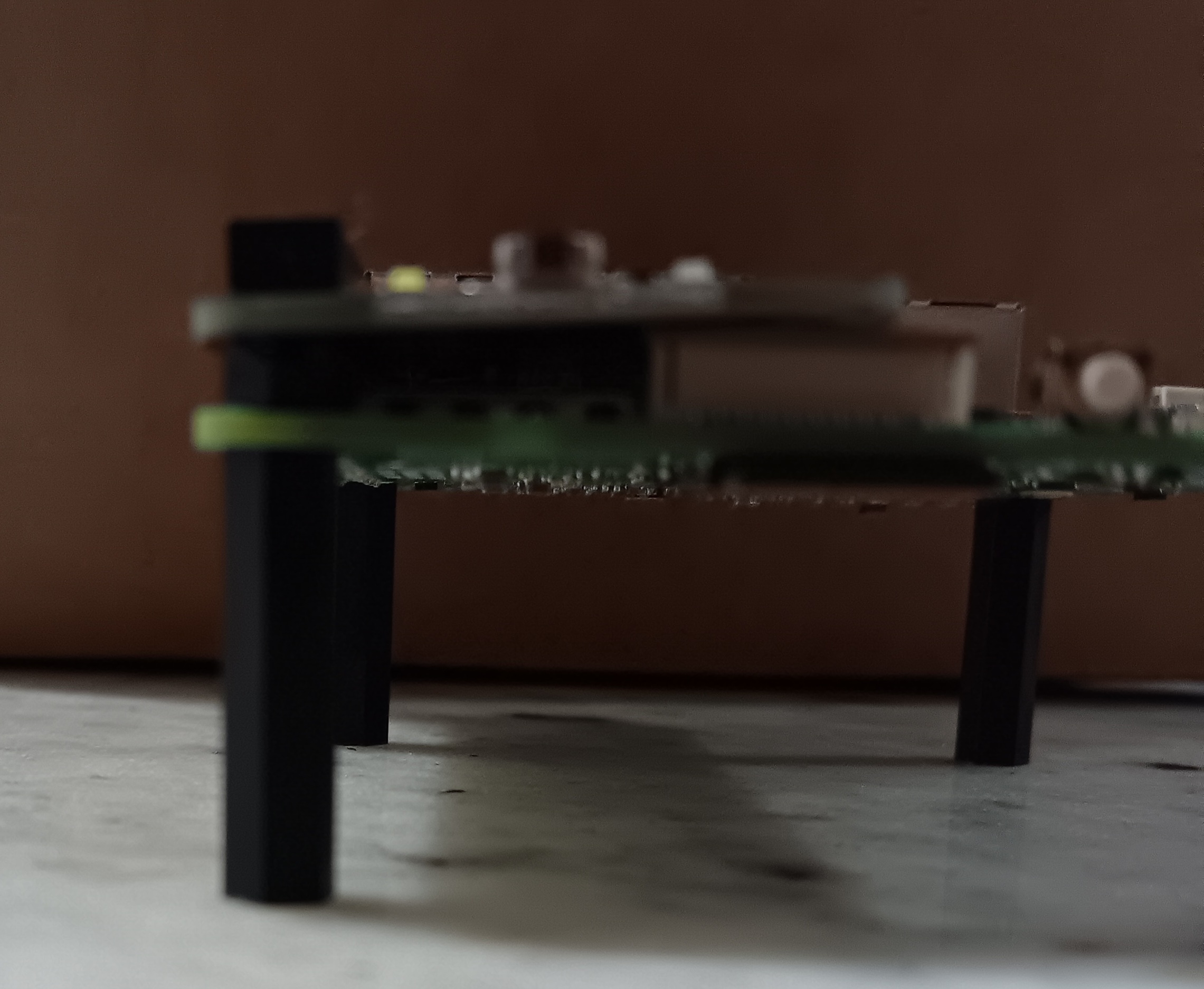
@jaykay The mechanical interference is caused by the Raspberry Pi 5 PCIe connector underneath the L3V7. So you were correct that the board cannot sit completely parallel when it is mounted directly on the Pi 5 header.
Please do not force the L3V7 down to make the boards parallel.
I also tested the same arrangement here. Even with the L3V7 slightly tilted by the PCIe connector, the Pi 5 was able to boot and the L3V7 was correctly detected on I2C at address 0x08. However, that does not guarantee that the electrical contact in your particular installation is equally reliable.
The recommended solution for this kind of mechanical interference is already described in the user manual (on page 10): use a 40-pin stacking header between the Raspberry Pi and the L3V7. This raises the L3V7 and allows it to sit parallel while maintaining reliable contact with all 40 pins.
After installing the stacking header, please power the system through the L3V7 as before and run:
i2cdetect -y 1
You should normally see the L3V7 at address 0x08.
If it still shows all dashes after the mechanical connection is corrected, please also post the output of:
gpio readall
@admin When mated fully it finally showed up...all ok. The stacking of the board creates a pretty warm CPU...My board will be a standalone. I believe I found a better way to control power and safe power turn downs using the MCU to monitor and a one shot 555. Once it gets that one shot from front panel momentary push button it will then looks what's going on. If PI not running (5v) then L3V7 with enable power to get PI going...then next one shot will shut off the PI in a sequence so the SD card does not get left with open files....graceful shut down.
No force applied to mate them but the board is in a CCW position on top of J20.
Jay
Here is the CCW position of board..resting on J20 and cutting off air flow of the CPU. Board now removed to be a standalone..
Thanks for advise.
Jay