Raspberry Pi is quite suitable for robot creation. Its GPIO pins could be used to control the motors and sensors, and itself could work as a server, and get controlled via Internet.
The Plan
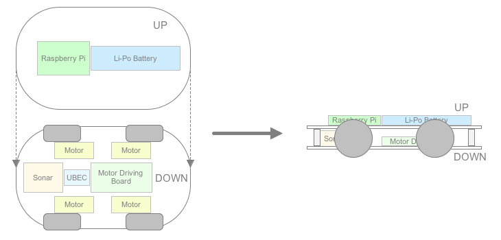
I am going to create a robot chassis, which could automatically avoid obstacle on the ground. Here is my plan:
Hardware Assembling
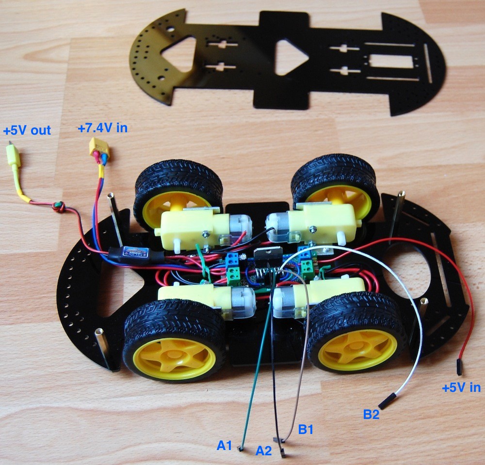
I bought a 4WD chassis kit from Internet. After assembling the kit, I got a 295mm x 150mm x 40mm chassis with 4 DC motors installed. The motors have built-in low gears and the actual speed is about 50 rpm, which is slow enough to avoid the calibration for the speed of each wheel. The 4 wheels have very soft tires, which improve the road holding, thus the chassis could get along on the slope.

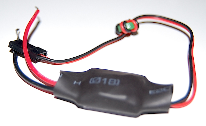
I will use a 7.4V Li-Po battery pack (2S) to power the entire chassis. In order to obtain 5V to power Raspberry Pi, I need a UBEC, which works like voltage regular but has much higher performance. UBEC is widely used by RF models, and has many types. In my case a 5V/3A UBEC is good enough.
Please notice that, using a 3A UBEC doesn’t mean you could really get 3A current in reality. The actual current that could be provided also limited by the Li-Po battery. When choosing the battery pack, please pay attention to its C rating value. What is C rating? C rating is a measurement for charge and discharge rates for battery, and 1C means 1 time the rated mAh capacity of the battery. Say you have 500mAh battery, then 1C means it could be charged/discharged with 500mA, while 2C means 1,000mA. My battery pack is 5,000mAh, 20-30C discharge, so it could provide up to 15A current. So in my case, the UBEC could really output 3A current.

The GPIO pin on Raspberry Pi can output signal but it is not capable to drive the DC motors. So I will need the motor driving board, which could be done by using a L298N IC. You can buy some ready-to-go driving boards from Internet, but I will just create a small board to do the job. The basic circuit diagram is shown below:
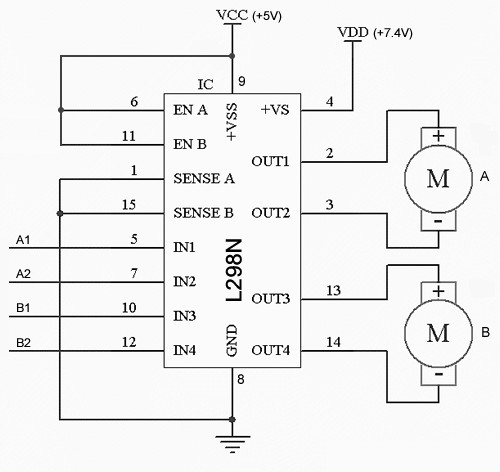
It is very simple and it can work without other components. If A1=1 and A2=0, motor A will go forward. If A1=0 and A2=1, motor A will go backward. If A1=A2, motor A will stop. B1, B2 just have the same behavior.
I can use two L298N ICs to control 4 DC motors, but it is not necessary in my case. The motor speed is quite low (by using the built-in gears), and the speed difference between motors could be ignored. So I could connect the two motors on the same side parallelly, and use only one L298N IC to drive the 4 motors (two groups).
I used a 3cm x 7cm universal PCB to finish the wiring:
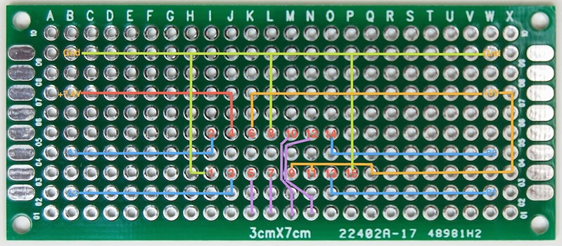
When the driving board get powered, it will draw quite a lot current at the first moment, and may cause the Raspberry Pi reboot (if you use the same power supply for both). To avoid this, a 100uF capacity is used between VCC and GND. The L298N IC is not soldered but plug into a modified IC slot. The +5V will be taken from the Raspberry Pi.
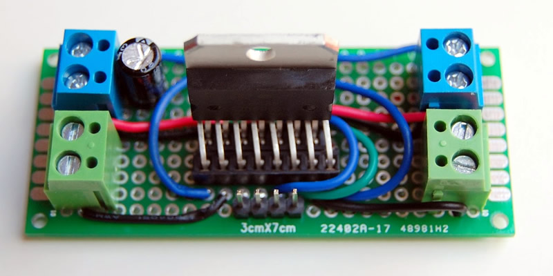
The connectors in green are for the motors (group A and B), while the connectors in blue are for power supply (+7.4V and +5V). I installed the driving board into the chassis. The UBEC is also connected to the +7.4V connector, so it can generate +5V to power Raspberry. Here I have to solder a micro-USB plug on the output of UBEC, so it could connect to Raspberry Pi. The +5V needed by the driving board will be taken from the +5V pin on Raspberry Pi.
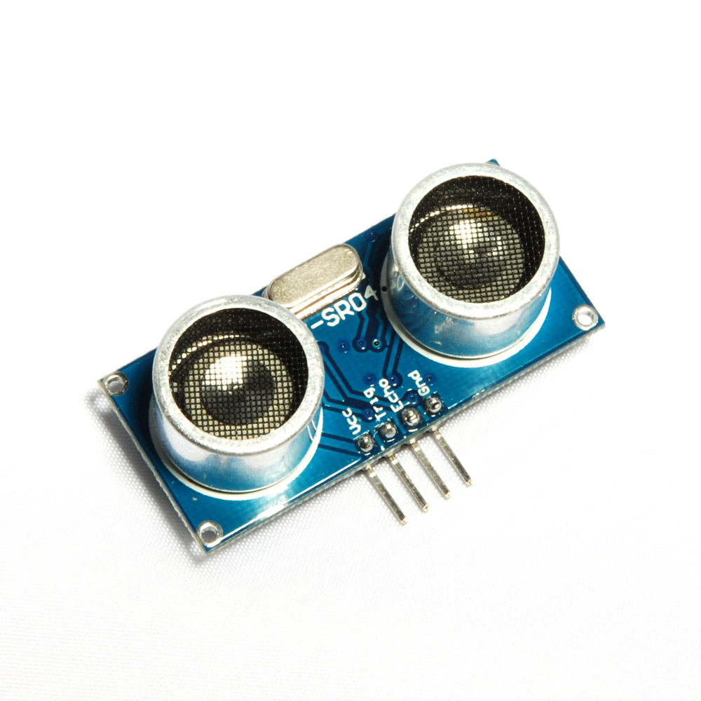
An ultrasound sensor is used to detect obstacle. It has four pins: VCC, Trig, Echo, and GND. To initialize the sensor, a pulse (at least 10us) should be sent to the Trig pin. After that we could wait and measure the width of the pulse on the Echo pin. The wider the pulse is, the longer distance is between the sensor and the object.
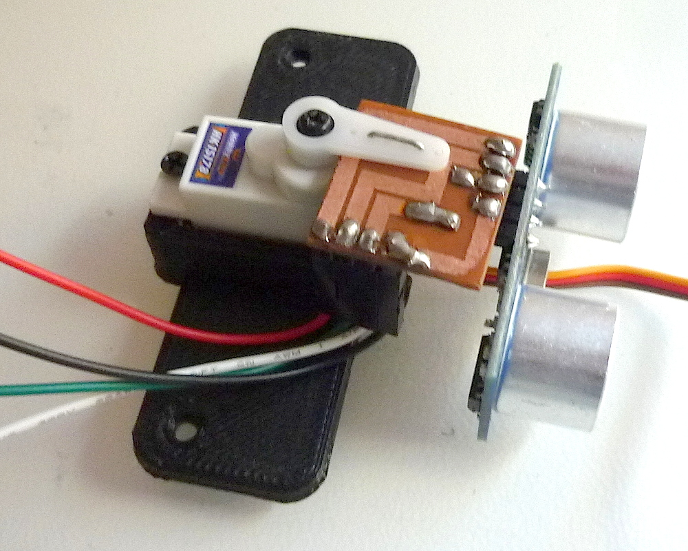
Measuring the distance of object in front of the chassis is not enough, as we need to define the strategy to make the chassis turn left or right. Hence the sensor should not be fixed on the chassis, instead it should be able to “look around” and face to different directions in front of the chassis. So I solder the sensor on a small PCB and then fix that PCB on a servo, which will then be mounted on the chassis. That small PCB also converts the output on Echo pin from 5V to 3.3V, by using two divider resistances. I need to do so because the GPIO pins on Raspberry Pi is working on 3.3V bias, while the Echo pin on the sensor could output 5V (as we powered it with 5V from Raspberry Pi). The plastic seat of the servo is made with my 3D printer. The servo could be SG-90 or other models that have similar size.
The servo’s signal line is connected to the GPIO 18 pin on Raspberry Pi, which is the only one that could generate PWM signal with hardware. You may wonder if it is safe to drive servo directly with the GPIO pin, the answer is positive. For Raspberry Pi, the recommended current for each GPIO pin is 3mA, and the maximum current is 16mA. While the servo’s signal line, will only draw about 0.02mA (i.e. 20uA) current, which is safe enough.
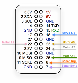
Here is how to wire the 7 used GPIO pins:
 And here is a picture of the real wiring:
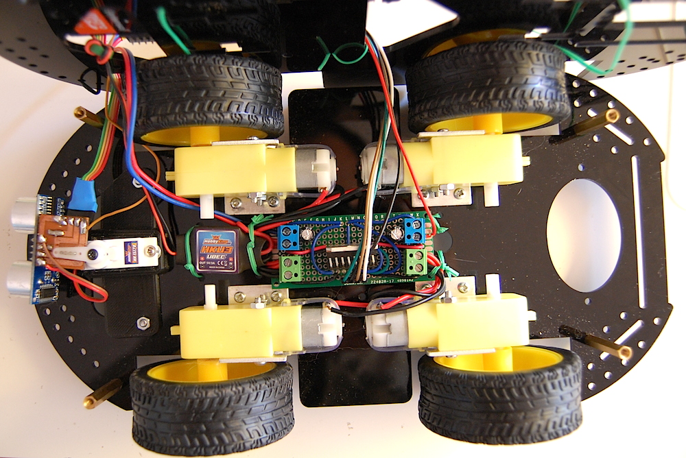
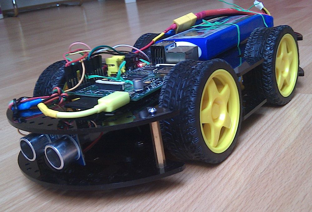
The Raspberry Pi and the Li-Po battery are placed on the upper plane. Here is how the whole chassis looks like:
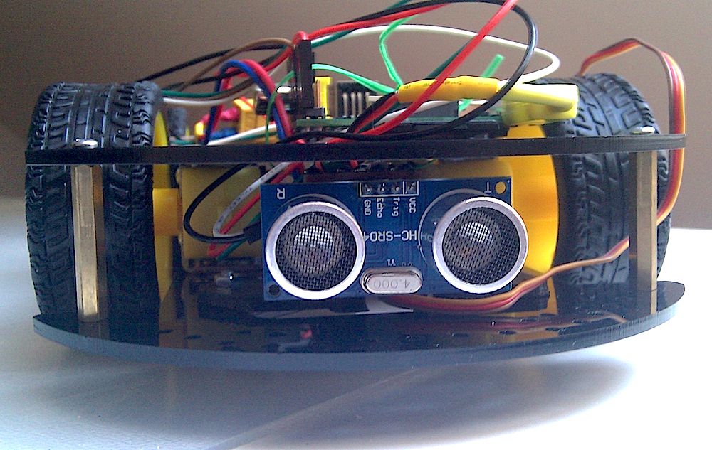
The ultrasound sensor looks like the robot’s big eyes:
Programming
The program is written in C language.
The first task is to drive the servo. I am using Frank Buss’s example, and put it in a header file:
// PWM example, based on code from http://elinux.org/RPi_Low-level_peripherals for the mmap part
// and http://www.raspberrypi.org/phpBB3/viewtopic.php?t=8467&p=124620 for PWM initialization
//
// Frank Buss, 2012
#define BCM2708_PERI_BASE	0x20000000
#define GPIO_BASE		(BCM2708_PERI_BASE + 0x200000) /* GPIO controller */
#define PWM_BASE		(BCM2708_PERI_BASE + 0x20C000) /* PWM controller */
#define CLOCK_BASE		(BCM2708_PERI_BASE + 0x101000)
#define	PWM_CTL  0
#define	PWM_RNG1 4
#define	PWM_DAT1 5
#define	PWMCLK_CNTL 40
#define	PWMCLK_DIV  41
#include <stdio.h>
#include <string.h>
#include <stdlib.h>
#include <dirent.h>
#include <fcntl.h>
#include <assert.h>
#include <sys/mman.h>
#include <sys/types.h>
#include <sys/stat.h>
#include <unistd.h>
#include <unistd.h>
#define PAGE_SIZE (4*1024)
#define BLOCK_SIZE (4*1024)
// I/O access
volatile unsigned *gpio;
volatile unsigned *pwm;
volatile unsigned *clk;
// GPIO setup macros. Always use INP_GPIO(x) before using OUT_GPIO(x) or SET_GPIO_ALT(x,y)
#define INP_GPIO(g) *(gpio+((g)/10)) &= ~(7<<(((g)%10)*3))
#define OUT_GPIO(g) *(gpio+((g)/10)) |=  (1<<(((g)%10)*3))
#define SET_GPIO_ALT(g,a) *(gpio+(((g)/10))) |= (((a)<=3?(a)+4:(a)==4?3:2)<<(((g)%10)*3))
#define GPIO_SET *(gpio+7)  // sets   bits which are 1 ignores bits which are 0
#define GPIO_CLR *(gpio+10) // clears bits which are 1 ignores bits which are 0
// map 4k register memory for direct access from user space and return a user space pointer to it
volatile unsigned *mapRegisterMemory(int base)
{
	static int mem_fd = 0;
	char *mem, *map;
	/* open /dev/mem */
	if (!mem_fd) {
		if ((mem_fd = open("/dev/mem", O_RDWR|O_SYNC) ) < 0) {
			printf("can't open /dev/mem \n");
			exit (-1);
		}
	}
	/* mmap register */
	// Allocate MAP block
	if ((mem = malloc(BLOCK_SIZE + (PAGE_SIZE-1))) == NULL) {
		printf("allocation error \n");
		exit (-1);
	}
	// Make sure pointer is on 4K boundary
	if ((unsigned long)mem % PAGE_SIZE)
		mem += PAGE_SIZE - ((unsigned long)mem % PAGE_SIZE);
	// Now map it
	map = (char *)mmap(
		(caddr_t)mem,
		BLOCK_SIZE,
		PROT_READ|PROT_WRITE,
		MAP_SHARED|MAP_FIXED,
		mem_fd,
		base
	);
	if ((long)map < 0) {
		printf("mmap error %d\n", (int)map);
		exit (-1);
	}
	// Always use volatile pointer!
	return (volatile unsigned *)map;
}
// set up a memory regions to access GPIO, PWM and the clock manager
void setupRegisterMemoryMappings()
{
	gpio = mapRegisterMemory(GPIO_BASE);
	pwm = mapRegisterMemory(PWM_BASE);
	clk = mapRegisterMemory(CLOCK_BASE);
}
void setServo(int percent)
{
	int bitCount;
	unsigned int bits = 0;
	// 32 bits = 2 milliseconds
	bitCount = 16 + 16 * percent / 100;
	if (bitCount > 32) bitCount = 32;
	if (bitCount < 1) bitCount = 1;
	bits = 0;
	while (bitCount) {
		bits <<= 1;
		bits |= 1;
		bitCount--;
	}
	*(pwm + PWM_DAT1) = bits;
}
// init hardware
void initHardware()
{
	// mmap register space
	setupRegisterMemoryMappings();
	// set PWM alternate function for GPIO18
	SET_GPIO_ALT(18, 5);
	// stop clock and waiting for busy flag doesn't work, so kill clock
	*(clk + PWMCLK_CNTL) = 0x5A000000 | (1 << 5);
	usleep(10);
	// set frequency
	// DIVI is the integer part of the divisor
	// the fractional part (DIVF) drops clock cycles to get the output frequency, bad for servo motors
	// 320 bits for one cycle of 20 milliseconds = 62.5 us per bit = 16 kHz
	int idiv = (int) (19200000.0f / 16000.0f);
	if (idiv < 1 || idiv > 0x1000) {
		printf("idiv out of range: %x\n", idiv);
		exit(-1);
	}
	*(clk + PWMCLK_DIV)  = 0x5A000000 | (idiv<<12);
	// source=osc and enable clock
	*(clk + PWMCLK_CNTL) = 0x5A000011;
	// disable PWM
	*(pwm + PWM_CTL) = 0;
	// needs some time until the PWM module gets disabled, without the delay the PWM module crashs
	usleep(10);
	// filled with 0 for 20 milliseconds = 320 bits
	*(pwm + PWM_RNG1) = 320;
	// 32 bits = 2 milliseconds, init with 1 millisecond
	setServo(0);
	// start PWM1 in serializer mode
	*(pwm + PWM_CTL) = 3;
}
After calling the initHardware() method, the setServo() method could be used to set the servo position.
The second part is distance measurement, or object detection. The GPIO 8 pin will be set high for 10us, and then the pulse width will be measured on GPIO 7 pin. The pulse width (in us) divided by 58 will be the distance (in cm) between sensor and the object.
In order to control GPIO pins, I used the WiringPi library, which allows me to easily set GPIO pin high/low. You may also notice that WiringPi project also has a library to support software PWM, which means any GPIO pin on Raspberry Pi could output PWM signal by using that library. The reason that I don’ use it, is that I only need one pin to generate the PWM signal, which is already provided by Raspberry Pi’s hardware, so I don’t want to use more CPU time to output the software PWM. However if your project needs multiple pins to output PWM signal, you could consider using this library, or use an Arduino as extension of Raspberry Pi to get more pins that can output PWM with hardware.
#include <stdio.h>
#include <stdlib.h>
#include <unistd.h>
#include <signal.h>
#include <string.h>
#include <errno.h>
#include <sys/time.h>
#include <wiringPi.h>
#define TRIGGER_PIN 8
#define ECHO_PIN 7
#define TIMEOUT 999 /* any value other than LOW or HIGH */
#define MIN_DISTANCE 3	// minimum distance: 3cm
#define MAX_DISTANCE 21	// maximum distance: 21cm
int initSonar()
{
	if (wiringPiSetupGpio () == -1)
    {
        fprintf (stderr, "Can't initialise wiringPi: %s\n", strerror (errno)) ;
        return 1 ;
    }
	return 0;
}
int waitforpin(int pin, int level, int timeout)
{
	struct timeval now, start;
	int done = 0;
	long micros = 0;
	gettimeofday(&start, NULL);
	while (!done)
	{
		gettimeofday(&now, NULL);
		if (now.tv_sec > start.tv_sec)
		{
			micros = 1000000L;
		}
		else
		{
			micros = 0;
		}
		micros = micros + (now.tv_usec - start.tv_usec);
		if (micros > timeout || digitalRead(pin) == level)
		{
			done=1;
		}
	}
	return micros;
}
float getAvgDistance(int testCount)
{
	float distance_sum = 0.0f;
	int actualCount = 0;
	int pulsewidth;
	pinMode(TRIGGER_PIN, OUTPUT);
	pinMode(ECHO_PIN, INPUT);
	int i;
	for (i = 0; i < testCount; i++)
	{
		/* trigger reading */
		digitalWrite(TRIGGER_PIN, HIGH);
		waitforpin(ECHO_PIN, TIMEOUT, 10); /* wait 10 microseconds */
		digitalWrite(TRIGGER_PIN, LOW);
		/* wait for reading to start */
		waitforpin(ECHO_PIN, HIGH, 5000); /* 5 ms timeout */
		if (digitalRead(ECHO_PIN) == HIGH)
		{
			pulsewidth = waitforpin(ECHO_PIN, LOW, 60000L); /* 60 ms timeout */
			if (digitalRead(ECHO_PIN) == LOW)
			{
				float dist = pulsewidth / 58;
				if (dist >= MIN_DISTANCE && dist <= MAX_DISTANCE) {
					distance_sum += dist;
					actualCount ++;
				}
			}
		}
	}
	if (actualCount == 0) {
		return 65535;	// no object detected
	}
	return distance_sum / actualCount;
}
The getAvgDistance() method accepts a parameter to indicate the number of tests that should be done before calculating the average distance. This will get much better result than measuring only once, in reality. This method also takes care of some error cases, if the result of measurement is out of a good range, it will drop that result.
I also put some methods in the “driver.h” header file, to control the motors:
#include <wiringPi.h>
#define MOTOR_A1 25
#define MOTOR_A2 24
#define MOTOR_B1 23
#define MOTOR_B2 22
void moveForward()
{
	digitalWrite(MOTOR_A1, HIGH);
	digitalWrite(MOTOR_A2, LOW);
	digitalWrite(MOTOR_B1, HIGH);
	digitalWrite(MOTOR_B2, LOW);
}
void moveBackward()
{
	digitalWrite(MOTOR_A1, LOW);
	digitalWrite(MOTOR_A2, HIGH);
	digitalWrite(MOTOR_B1, LOW);
	digitalWrite(MOTOR_B2, HIGH);
}
void stopMoving()
{
	digitalWrite(MOTOR_A1, LOW);
	digitalWrite(MOTOR_A2, LOW);
	digitalWrite(MOTOR_B1, LOW);
	digitalWrite(MOTOR_B2, LOW);
}
void turnRight()
{
	digitalWrite(MOTOR_A1, HIGH);
	digitalWrite(MOTOR_A2, LOW);
	digitalWrite(MOTOR_B1, LOW);
	digitalWrite(MOTOR_B2, HIGH);
}
void turnLeft()
{
	digitalWrite(MOTOR_A1, LOW);
	digitalWrite(MOTOR_A2, HIGH);
	digitalWrite(MOTOR_B1, HIGH);
	digitalWrite(MOTOR_B2, LOW);
}
int initDriver()
{
    if (wiringPiSetupGpio () == -1)
    {
            fprintf (stderr, "Can't initialise wiringPi: %s\n", strerror (errno)) ;
            return 1 ;
    }
    pinMode(MOTOR_A1, OUTPUT);
    pinMode(MOTOR_A2, OUTPUT);
    pinMode(MOTOR_B1, OUTPUT);
    pinMode(MOTOR_B2, OUTPUT);
    stopMoving();
    return 0;
}
Below is the main program of the chassis, which includes the 3 header files above.
It starts a new thread to keep collecting the data from sonar sensor, which is rotated by the servo. The servo can have 11 possible positions (from 0% to 100%, 10% per step), the distance data will be stored in an array that has 11 elements. The main thread of the application, will keep checking the data in that array, and decide which direction is the better one to go ahead. In case all directions are bad, the chassis will back off, and try again later.
#include <unistd.h>
#include <signal.h>
#include <pthread.h>
#include "servo.h"
#include "sonar.h"
#include "driver.h"
// arrays to store raw data
float raw[11];
// arrays to store processed data
float dist[11];
// before exiting, reset servo position and stop moving
void sig_handler(int signo)
{
	setServo(50);
	stopMoving();
	exit(0);
}
// initialize the data
void init_data()
{
    int j;
    for (j = 0; j < 11; j ++)
    {
        raw[j] = 0;
        dist[j] = 100;
    }
}
// call this method to collect and process data
void * collect_data(void * argument)
{
	int scanDir = 1;
	while (1)
	{
		int i;
		for (i = 0; i <= 10; i ++)
		{
			int ratio = i * scanDir + (scanDir < 0 ? 10 : 0);
			setServo(ratio * 10);
			usleep(10000);	// this controls how fast the sonar scan
			raw[ratio] = getAvgDistance(3) ;
			dist[ratio] = raw[ratio] <= 20 ? 0 : 100;
		}
		scanDir = -scanDir;
	}
}
// return 1 if there is any object detected
int detectedAnyObject()
{
	int i;
	for (i = 0; i <= 10; i ++)
	{
		if (dist[i] == 0)
		{
			return 1;
		}
	}
	return 0;
}
// move the chassis back, turn left/right at the same time
void backOff(int left, int steps)
{
	int k;
	for (k = 1; k <= steps; k ++)
	{
		if (left > 0)
		{
			turnLeft();
		}
		else
		{
			turnRight();
		}
		usleep(k * 10000);
		moveBackward();
		usleep(k * 10000);
	}
}
// main entrance
int main(int argc, char **argv)
{
	// init PWM module for GPIO pin 18 with 50 Hz frequency
	initHardware();
	// init sonar
	initSonar();
	// init driver
	initDriver();
	// reset status before exiting
	signal(SIGINT, sig_handler);
	signal(SIGHUP, sig_handler);
	signal(SIGKILL, sig_handler);
	signal(SIGTERM, sig_handler);
	// start thread to collect data
	init_data();
	pthread_t thread;
	int rc = pthread_create(&thread, NULL, collect_data, NULL);
	int minSpeed = 5000;
	int maxSpeed = 20000;
	int curSpeed = minSpeed;
	while (1)
	{
		// adjust direction
		float frontDist = dist[5] * 0.4 + dist[4] * 0.2 + dist[6] * 0.2 + dist[3] * 0.1 + dist[7] * 0.1;
		float rightDist = dist[0] * 0.5 + dist[1] * 0.3 + dist[2] * 0.2;
		float leftDist = dist[10] * 0.5 + dist[9] * 0.3 + dist[8] * 0.2;
		printf("%.2f : %.2f : %.2f <> %d \n", leftDist, frontDist, rightDist, curSpeed );
		if (frontDist > 30) {
			moveForward();
			if (!detectedAnyObject())
			{
				if (curSpeed < maxSpeed)
				{
					curSpeed += 100;
				}
			}
			else
			{
				if (curSpeed > minSpeed)
                {
					curSpeed -= 100;
                }
			}
		} else {
			curSpeed = minSpeed;
			if (rightDist > leftDist) {
				turnRight();
			} else if (rightDist < leftDist) {
				turnLeft();
			} else if (rightDist <= 30) {
				double random_number = rand() / (double)RAND_MAX;
				backOff(random_number > 0.5 ? 1 : 0, 10);
			} else {
				stopMoving();
			}
		}
		usleep(curSpeed);
		stopMoving();
		usleep(5000 - (curSpeed - 5000) / 3);
    }
    return 0;
}
To compile it, in Raspberry Pi console you run:
cc -o cruise cruise.c -lwiringPi
You can also check out the videos on the right sidebar, to see how it works.